

A rubber track order usually starts with three numbers. Getting those numbers right is straightforward when the marking is clear. The harder jobs involve a worn sidewall, a missing section, an unfamiliar guide profile or two suppliers offering slightly different sizes for the same machine.
This guide takes you from the marking to a usable measurement record. It covers continuous rubber tracks on mini excavators and compact tracked equipment. Steel chains fitted with rubber pads, over-the-tire tracks and agricultural track systems need their own product identification methods. Where a manufacturer uses a different marking order, its product documentation takes priority.
The images are original AI-generated instructional illustrations. They show measurement relationships and example features, rather than a certified product drawing or a particular machine’s approved replacement.
Quick Answer
- Find the full molded code first. Photograph the complete marking, including letters and the manufacturer’s name. A common format is width × pitch × link count.
- Measure width across the belt. Use an intact section of the rubber body and record millimeters. Avoid a torn edge or an angled tape.
- Measure pitch along the inner engagement features. Use matching reference points on adjacent links. For a clearer reading, measure several complete intervals and divide by the number of intervals.
- Count the internal link stations around the whole loop. Mark your starting station and count it once. Paired guide horns may belong to one station; outer tread blocks are a separate pattern.
- Finish with the guide profile and machine identity. Give the supplier your measurements, inner-track photographs and complete model/serial information so the proposed part can be matched to the actual undercarriage.
For example, 300 × 52.5 × 80, in width–pitch–links order, means a 300 mm width, 52.5 mm pitch and 80 links. The final number is a count, not a length. Additional characters can identify construction or guiding details, so keep them in the record.
Read the Rubber Track Size Code Before Measuring
What the three numbers mean
Most compact-equipment replacement listings organize rubber track sizes by width, pitch and link count. Width runs across the machine’s direction of travel. Pitch runs along it, between repeating internal engagement features. The link count describes how many specified internal stations make up the loop. Rubbertrax’s measurement guide uses this format and separates guide-system measurements from the three size fields.
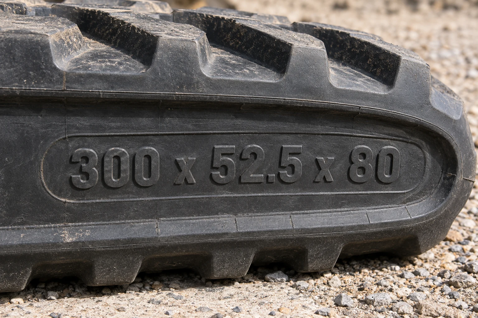
Illustrative size marking. Read each field according to the track manufacturer’s marking system; this example uses width × pitch × links.
| Field in the example | Meaning | What you record | What it helps resolve |
|---|---|---|---|
| 300 | Nominal belt width | 300 mm | Width family and clearance discussion |
| 52.5 | Nominal internal pitch | 52.5 mm | Repeating engagement spacing |
| 80 | Link stations in the loop | 80 links | Loop configuration within that pitch family |
| Any additional characters | Product-specific designation | Complete characters, unchanged | Guide, construction or tread variant according to the maker |
A useful record keeps the code exactly as found and puts your interpretation beside it. For example: “Molded text: 300 × 52.5 × 80; interpreted as width 300 mm, pitch 52.5 mm, count 80.” This preserves the original evidence if a supplier needs to read it differently. It also prevents a phone conversation from turning a decimal pitch into a whole number.
A size code and a part number serve different purposes. The size describes selected dimensions. A part number identifies a particular item within a manufacturer’s system. A production or batch code may help trace manufacture. When several strings appear in the rubber, photograph the group before deciding which one is relevant. Janssen Track’s identification guide specifically distinguishes size markings from serial, production and part numbers.
Keep letters, punctuation and brand information
A search box may accept only three numbers, but your enquiry should retain the rest of the designation. A letter between the pitch and count can carry useful information. Other suppliers put construction identifiers after the dimensions or use a more extensive part-number format.
For a documented example, MST’s measuring sheet shows a 300 × 52.5 × 78 track with a wide-gauge designation and a separate guide measurement. Use that as an example of why the extra information matters, rather than a universal decoder for every manufacturer’s letters. Bridgestone describes a five-element track identification system, which is another reason to retain the complete marking.
If the last character could be an S, a 5 or a damaged 8, put a question mark in your notes and attach a close-up. A clearly labeled uncertainty is easier to resolve than a confidently mistyped identifier. I would keep both the close-up and a wider image showing where the marking sits on the track; the wider view helps distinguish an isolated batch stamp from a complete product designation.
Check the order instead of assuming it
Width–pitch–links is the convention used throughout this guide. It is an interpretation format, not a rule you should impose on every string molded into rubber. Some product designations arrange fields differently or include additional information in the middle. Read the maker’s legend when the numbers appear in an unexpected order.
A quick physical check helps. If a code appears to describe a width much smaller than the belt you can see, something has probably been transposed or misread. That observation tells you to investigate the legend; it does not justify swapping fields until the result resembles a familiar online listing. Save the unchanged marking alongside your measured dimensions so the discrepancy stays visible.
Prepare the Track, Tools and Measurement Record
Choose an accessible, stable measuring position
An already removed track, lying securely on firm level ground with a straight section accessible, is a useful starting point. You can see its inner features without reaching into the undercarriage. Keep clear of a loop that could roll, fold or fall, and leave lifting or repositioning heavy tracks to suitable equipment and trained personnel.
For a fitted track, collect only what is safely accessible with the machine secured under its operating and service instructions. Shut down and isolate movement as the manual requires. Keep fingers and measuring tools away from sprocket, idler and roller pinch points. If hidden sections require lifting or rotating the machine’s track, use the model’s service procedure or have a qualified technician complete that part of the record. The machine manual supplies the lifting arrangement and any permitted rotation procedure.
That distinction makes the job easier to plan. You can often photograph the machine plate, read exposed markings and measure accessible width before any service work is arranged. A partial record with “link count pending safe access” is more useful than taking an avoidable risk to fill a box. Send the partial information if the supplier can begin a catalog search while the remaining measurement is obtained.
Tools and what each contributes
| Tool or information | Use | Practical detail |
|---|---|---|
| Metric steel rule or tape | Width and multi-interval span | Check that the zero point and graduations are readable |
| Chalk or removable marker | Start station and counting groups | Use a clear mark that cannot be confused with old marks |
| Brush and cloth | Expose markings and reference surfaces | Remove loose dirt without damaging rubber or metal |
| Camera or phone | Record endpoints, profile and identifiers | Keep the lens square to the measurement plane where possible |
| Caliper, when suitable | Accessible guide dimensions and short spans | Identify the exact surfaces being measured before closing the jaws |
| Machine identification | Catalog and configuration match | Record the full model suffix and serial/PIN from the machine |
| Simple worksheet | Keep observations separate from assumptions | Label units and identify which track side was measured |
A caliper is useful when its range and access suit the feature. It is unnecessary for a broad width that a straight ruler can show clearly. More decimal places on a display do not make an irregular, worn rubber edge precise. Match the tool to the measurement, and describe the condition of the surface it touched.
Before starting, look at the ruler’s zero. A damaged tape hook, a cropped photograph or a rule placed at the 100 mm mark can cause a large recording error. Starting at 100 mm is acceptable if you record both readings and subtract them. Writing only the far-end reading would add 100 mm to the result. The worked examples below deliberately retain start and end readings to make this kind of error visible.
Separate observed, calculated and confirmed information
Use three categories in your notes. Observed information comes from the track or machine: a marking, a count, a photographed span. Calculated information includes a multi-interval pitch or an inch conversion. Confirmed information comes from a documented catalog match or the supplier’s identification of the replacement.
This separation is particularly helpful with worn tracks. You might observe widths of 298, 299 and 300 mm, calculate a pitch of 52.5 mm and receive confirmation of a 300 mm nominal replacement. All three stages belong in the record. Replacing the original readings with a clean “300” hides the condition that made you uncertain in the first place.
For a fleet, add an equipment asset number and the measured side. Two similar machines parked together can have different configurations. A track photograph named only “new track” is difficult to use later. An asset number, side and date allow a buyer, fitter and supplier to discuss the same item without repeating the measurement session.
Step 1: Measure Rubber Track Width
Measure squarely across intact rubber
Place the rule across the belt, perpendicular to its length, with both outside edges visible. Take the width from an intact part of the rubber body. Keep the rule in a plane that represents the full width, rather than resting it diagonally across tread peaks or using a narrower worn feature as the edge.
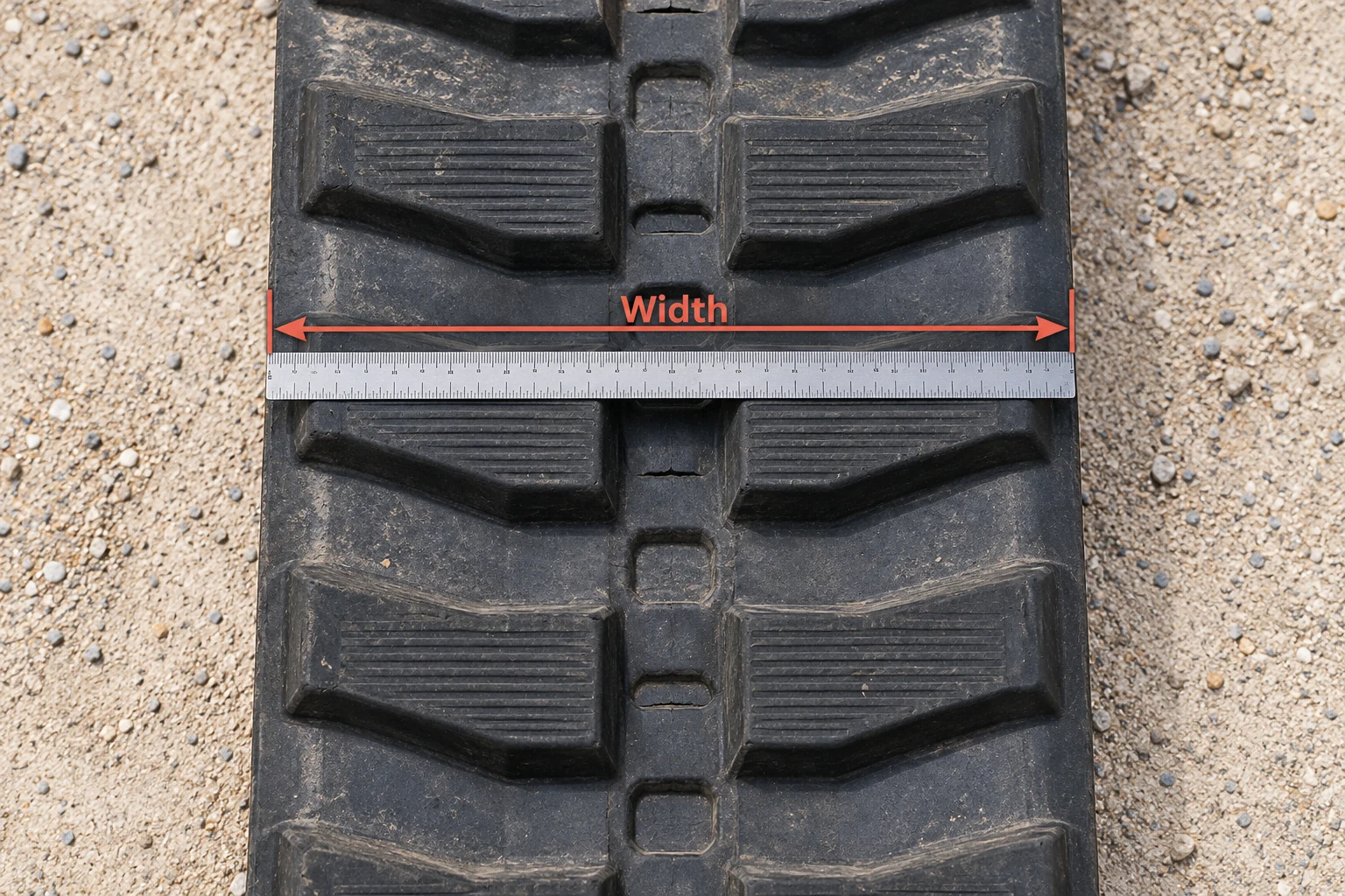
Width crosses the belt. The illustration shows the direction and endpoints; use your own ruler reading for the actual measurement.
Take readings at several accessible positions when the edge condition varies. You are looking for a consistent body width and an explanation for any smaller reading. A missing piece on one side can make a nominally wider belt resemble a narrower option. A bulge, loose flap or embedded debris can produce the opposite impression.
A useful photograph shows the whole width and both endpoints. If the markings are too small to read in that frame, add close-ups of each end without moving the rule. A picture showing only the far edge leaves the starting position unverified. For a remote supplier, seeing the zero and the endpoint is usually more helpful than a sharply focused image of one number.
Nominal width and a worn measurement
Treat nominal width as a product specification, and your measurement as an observation of the item in front of you. A damaged track need not measure exactly like a new one. The buying decision is to identify the intended specification, supported by the marking, intact areas and machine configuration.
Suppose three intact-looking sections give 299, 300 and 299 mm, while a fourth torn section reads 292 mm. Those observations support investigating a 300 mm nominal track. They do not support selecting a 290 mm track because one damaged section is closer to that number. Record the damage and retain the photographs so the supplier can see the basis of the proposed size.
Avoid a universal “round to the nearest ten” rule. It conceals the difference between a measurement estimate and an approved size, and it fails for products specified in other increments. If your reading lies between available choices, the next useful step is checking the full designation and catalog match. Forcing the reading into a familiar number can create a convincing but wrong record.
Width changes are a configuration decision
A wider belt may be offered for some machines, but a wider measurement alone tells you little about whether a conversion is permitted. The undercarriage, clearances, approved track options and operating arrangement have to support it. An owner replacing like-for-like should identify the existing approved configuration first.
For example, a machine that must pass through a narrow gate has a width constraint beyond the individual belt. The outside machine width depends on the chassis arrangement and track position as well as track width. An extending undercarriage adds another dimension. Keep “rubber belt width” and “overall machine width” in separate fields so a site-access question does not get mistaken for a replacement specification.
If you are considering a different width, ask for the approved alternative for that exact machine and configuration. Give the supplier the practical reason—clearance, flotation or a surface requirement—rather than asking them to choose the widest belt that appears to fit. That produces a more useful discussion about options and limits.
Step 2: Measure Pitch Between Matching Internal Features
Find the repeat that engages the undercarriage
Pitch describes a repeated spacing along the track. On the compact-equipment steel-core rubber tracks discussed here, the identification measurement follows the internal links or corresponding engagement features. Choose the same point on successive stations, using the manufacturer’s drawing to resolve an unfamiliar construction. Vematrack’s measuring guide illustrates an internal center-to-center measurement with a tape or caliper.
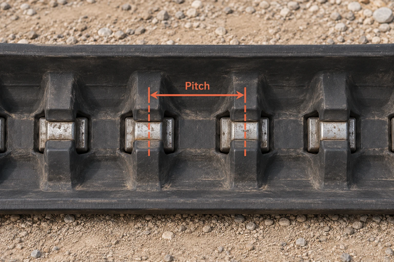
Pitch is measured along the belt between equivalent points on adjacent internal stations. The outside tread pattern serves a different purpose.
Center-to-center is easy to describe but can be awkward to judge on rounded or partly covered features. When two undamaged features have the same geometry, corresponding edges can provide the same repeat distance: left edge to the next left edge, for example. Keep the reference consistent. Measuring from the left edge of one feature to the right edge of the next adds feature width to the pitch.
Imagine two identical marks centered at 20 and 72.5 mm. Their center spacing is 52.5 mm. If both marks are 10 mm wide, their left edges sit at 15 and 67.5 mm, which also differ by 52.5 mm. Mixing the first left edge and second right edge would produce 62.5 mm. This arithmetic example explains the reference-point problem; it is not a track tolerance or a feature dimension to use on your machine.
Measure several intervals when one is difficult to read
A longer span can make a small pitch difference easier to see. Select a reasonably straight, accessible section, identify matching points and record the total span across several complete intervals. Divide that span by the number of intervals. Group HES’s measuring sheet includes a multiple-interval method alongside its width and link-count instructions.
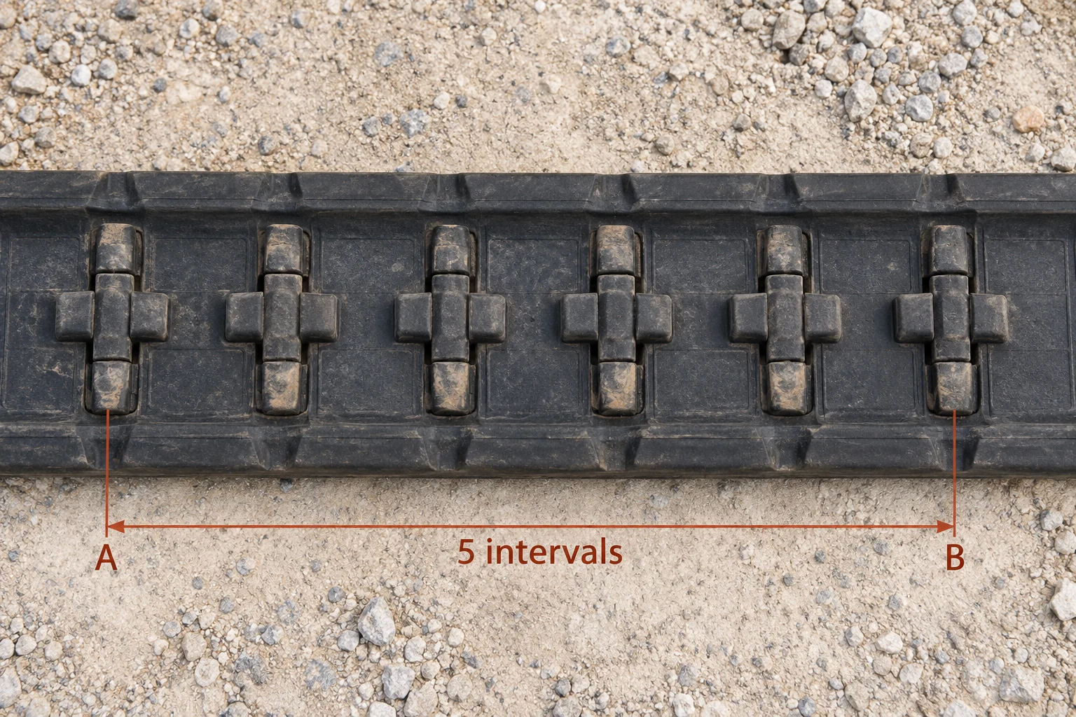
Six station centers enclose five intervals. Divide the A-to-B span by five, not six.
The distinction between stations and spaces is the most important part of this method. From station 1 to station 2 there is one interval. From station 1 to station 6 there are five. A drawing with six visible stations is not a six-pitch measurement unless the endpoints enclose six actual spaces.
Pitch = measured span ÷ number of intervals.
| Your endpoints | Intervals enclosed | Illustrative span | Calculated pitch |
|---|---|---|---|
| Center 1 to center 2 | 1 | 52.5 mm | 52.5 mm |
| Center 1 to center 6 | 5 | 262.5 mm | 52.5 mm |
| Center 1 to center 11 | 10 | 525 mm | 52.5 mm |
These are mathematical examples of one pitch, not separate suggested sizes. Choose a span that is accessible and straight enough to measure properly. There is little benefit in extending the measurement around a curve just to include more stations. If a long straight section is unavailable, a shorter well-defined span can be more dependable than a poorly positioned long one.
Record the start reading, end reading and interval count
Suppose your first reference point aligns with 100 mm on the rule and your sixth aligns with 362.5 mm. The span is 362.5 − 100 = 262.5 mm. Divide by five intervals to obtain 52.5 mm. Recording only “362.5” loses the starting offset and would lead to the wrong result.
Make a second reading on another suitable section where possible. If one measurement gives 52.5 mm and another gives 55 mm, investigate the endpoints, interval count, track position and damaged features before averaging the results. Averaging a correct reading with an incorrectly counted span produces a third number that may correspond to neither observation.
For remote review, a marked photograph should show the two endpoints and the intermediate stations. A supplier can then count the intervals themselves. If the full frame cannot show readable ruler graduations, add endpoint close-ups and keep the original wide frame. Those three images provide the context and the numerical detail needed to interpret the result.
What a longer span improves—and what it cannot fix
Consider an illustrative reading uncertainty of ±2 mm in the total span. Over one interval, that means ±2 mm in the calculated pitch. Over five intervals, dividing by five gives ±0.4 mm. Over ten intervals, it gives ±0.2 mm. This is arithmetic propagation of a stated span uncertainty, not a claim that any particular tape measure or field technique achieves those figures.
The method helps when the main problem is judging the endpoints. It will not correct an incorrectly identified repeat, a twisted section, a miscounted number of intervals or a ruler held at the wrong angle. A longer measurement can still be systematically wrong. Repeatability, clear reference points and the maker’s intended geometry matter alongside the number of intervals.
Keep decimal pitches exactly as documented. A 52.5 mm result should not become 53 mm because the enquiry form accepts only whole numbers. Add the correct value in the message or use another ordering channel. Fortes’ guide highlights fractional pitches and illustrates why measuring across multiple links helps distinguish close values.
Step 3: Count the Internal Links Around the Loop
Mark one station and count it once
Start with a clearly identified internal station. Mark it, record it as number one and count the subsequent stations around the complete track. Stop before counting the starting mark a second time. A second count, preferably using independently recorded groups, is worthwhile because an off-by-one result is easy to make on a repetitive surface.
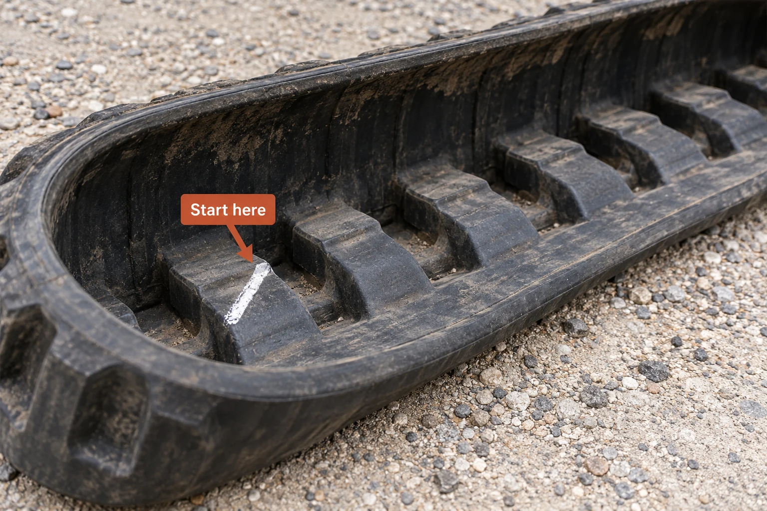
Choose one unambiguous starting station. The chalk mark organizes the count; it does not establish the track’s specification.
For a long loop, mark small groups as you go and write down the group totals. For example, seven complete groups of ten plus eight remaining stations gives 78. Keep the first station within the first group rather than adding it again at the end. If you stop midway, a written subtotal and a distinct temporary checkpoint are safer than relying on memory.
Two people can make this process easier, but both need to use the same counting unit. One person can identify stations while the other records groups. Afterward, change roles or start from a different mark for an independent check. An independent recount can catch a skipped station that both people missed during the first pass.
Paired horns are not necessarily two links
Some tracks show two guide projections across a single internal station. Counting every visible projection as a separate link would double the result for that arrangement. Identify the station that repeats along the direction of travel, rather than counting left and right features independently. MST’s illustrated procedure explicitly describes pairs in its example track.
This is where a photograph of the whole inner width is useful. It shows whether two projections belong to one repeating cross-track feature or whether you are looking at another design. If the arrangement is unfamiliar, ask the manufacturer or supplier to mark the intended counting unit on your photograph. That is more reliable than debating whether a feature should be called a lug, link, bar or horn.
Outer tread blocks also make a poor default counting unit. Their layout can include staggered bars, split blocks or a pattern that differs from the internal repeat. The visible ground-contact pattern is useful when choosing traction characteristics, but the ordering link count follows the track’s specified internal construction.
Handle missing pieces without inventing a total
A torn belt may still retain every internal station. If the full material is present and safely accessible, the count may be recoverable across the separated pieces. Assign each piece an identifier and photograph its ends before adding the subtotals. Account for whether a station at a fracture has been split between two pieces so it is not counted twice.
When material is missing, record the number of stations present and say that the total is incomplete. The missing count needs another source: a readable marking, an established part number, the machine’s documented configuration or a properly identified counterpart. A guessed count based on the apparent length of the missing gap can send a supplier toward the wrong product.
A matching track on the other side can be useful evidence, especially if its marking survives. However, keep the side identifiers in the record and check whether earlier repairs introduced different products. “Left side marked 80; right side incomplete count” is honest and actionable. “Both tracks are 80” implies verification that has not yet happened.
Step 4: Record the Guide Profile and Roller Relationship
The three numbers leave out some geometry
Once width, pitch and count are known, photograph the inside of the track squarely across its width. Include the guide arrangement, engagement area and running surfaces. Depending on the product family, the supplier may need dimensions such as guide spacing, guide height or a defined rail profile.
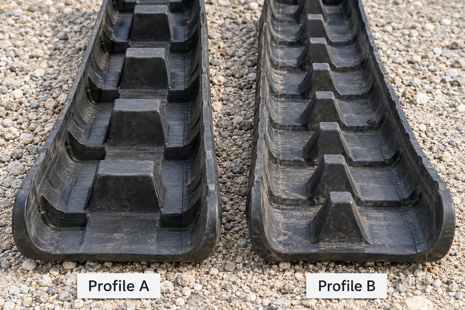
Illustrative guide profiles A and B. These labels distinguish the pictures only; they are not manufacturer classifications or a compatibility chart.
A guide dimension should name the surfaces it connects. “Gap: 46 mm” is incomplete if the supplier needs the gap at the base and you measured between rounded tips. Label the measurement on a photograph or drawing, state the tool used and describe any wear. When a supplier supplies a dimensioned sketch, use that sketch’s reference letters in your response rather than inventing a second A/B/C scheme.
The Camso construction catalog separates width, pitch and links from tread, guiding and metal-piece information. That structure is useful evidence that a dimensional summary and a specific product configuration are different levels of identification. An older catalog can explain the fields, while current availability and the replacement for your machine still need a current lookup.
Include the roller contact area in your photographs
If the existing belt has rubbed unevenly or the guide features look damaged, show the corresponding roller or guide area as well as the track. A close-up of the belt alone may leave the supplier unable to identify which configuration it was running against. The machine’s undercarriage parts and their locations are shown in our excavator parts diagram.
You do not need to dismantle a roller to complete a routine track enquiry. The useful first step is documenting what can be seen safely: the roller profile, the track’s running path and any obvious differences between sides. If the hardware has been converted or replaced, say so. A catalog entry for an original configuration can be misleading when the actual undercarriage has changed.
For a replacement decision, it helps to separate two questions. First, which belt construction belongs on this configuration? Second, is the supporting undercarriage in a condition that can accept the new belt? A dimensional match answers part of the first question. Wear assessment addresses the second. Combining them into one vague “will it fit?” question makes the response less precise.
Ask for the complete proposed designation
A useful supplier reply identifies the proposed product by its full designation or part number and states the machine/configuration used for the match. If the reply quotes only “300 track,” ask for the missing pitch, count and variant information before ordering. That clarification can be short and specific.
For example: “Please quote the complete track designation and confirm which inner guide profile it uses. The attached photo shows the current running surface and the machine identification plate.” This keeps the conversation on the unresolved item. There is no need to resend every dimension if the supplier has already acknowledged them correctly.
For buyers comparing two offers, copy the specifications into separate columns without normalizing away suffixes. A difference may be a valid alternative construction, a supplier’s own numbering system or a genuine mismatch. Resolve the meaning first; compare price after the offered products are understood.
When the Code Is Missing, Worn or Conflicts With the Measurements
Use the strongest surviving evidence for each field
A damaged belt may provide a reliable pitch, an unreliable width and no readable size code. Treat those as three separate findings. There is no requirement for one source to answer everything. The machine record may establish the approved width while the surviving loop allows a complete link count.
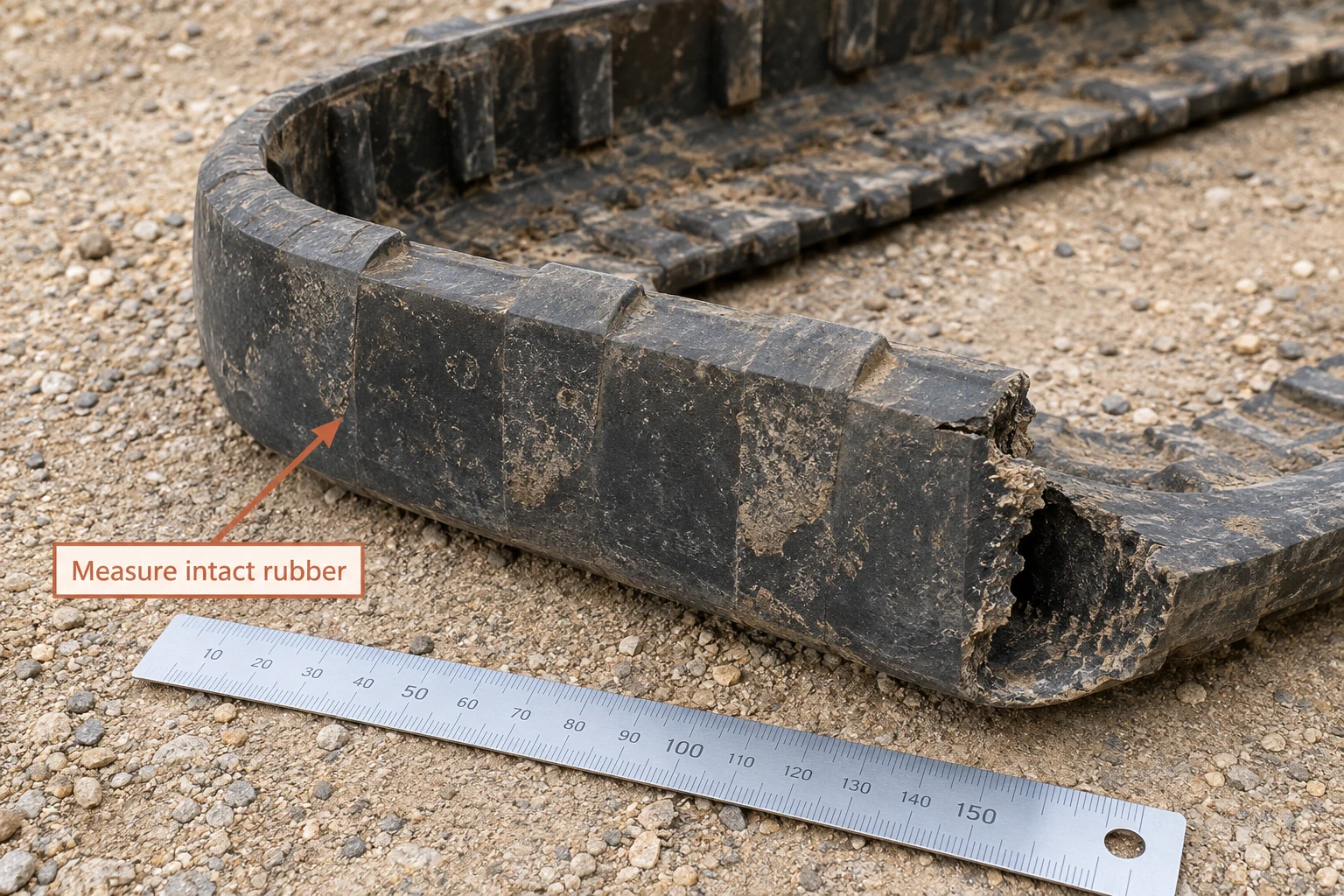
Damage can obscure original boundaries. Select intact reference areas and record what is missing; the illustration is not a scale drawing or a serviceability assessment.
| Situation | Useful evidence to collect | What remains unresolved |
|---|---|---|
| Size marking has worn away | Width, multi-interval pitch, complete count, inner profile | Exact product variant until matched |
| One edge is torn | Intact width readings, original marking if present | Nominal width if every section is damaged |
| Track is split but all pieces remain | Piece photos, station subtotals, fracture locations | Any ambiguous split station |
| A section is missing | Surviving code, machine configuration, opposite-side evidence | Original total count unless independently established |
| Code and measured pitch disagree | Uncropped code photo and marked pitch endpoints | Whether the problem is reading, order or measurement |
| Seller’s application listing disagrees | Full model suffix, serial/PIN, prior replacement history | Correct catalog application for the actual configuration |
If the molded number is legible but one measured value differs, check the measuring method first. A curved span, mixed endpoints or wrong field order can explain an apparent mismatch. If the measurements remain consistently different, send both forms of evidence. Silently editing the observations to agree with the marking removes the very discrepancy the supplier needs to investigate.
Do not reconstruct a size from machine weight alone
Machine weight is too broad a filter for identifying a rubber track. Equipment in the same general size class can use different undercarriage arrangements, pitches and counts. Weight may help a seller navigate a product family, but the replacement decision needs machine and track information.
Likewise, a model nickname can cover several revisions or configurations. Record the complete designation as it appears on the machine, including letters after the main number. If the machine plate is unreadable, collect the available records and photographs rather than filling in the most familiar suffix from an advertisement.
An old invoice can be valuable if it identifies the actual replacement previously installed. Keep its date and the supplier’s part number. An invoice for the same fleet’s other machine is only a lead until the asset is matched. This is a record-management problem as much as a measuring problem, and it becomes more common when several similar machines share a workshop.
Three worked identification cases
Case A: readable marking, routine replacement. An owner records a clear 300 × 52.5 × 80 marking, retains the remaining letters, measures approximately 300 mm across intact rubber and confirms 80 internal stations. The inner-profile photos and machine plate accompany the enquiry. The next task is a catalog/configuration match, not another round of generic measuring advice.
Case B: worn marking, close pitch values. A buyer can read the width and count but cannot distinguish the pitch characters. Five measured intervals span 262.5 mm, giving 52.5 mm. A second straight section gives the same result. The buyer sends both endpoint photographs instead of rounding the pitch to a nearby whole number. The calculation strengthens identification while leaving the product variant for confirmation.
Case C: incomplete belt, no dependable count. A track has broken and a piece is missing. The surviving material provides width and pitch observations, but the count is recorded as incomplete. The supplier uses the complete machine identity and documented undercarriage configuration to propose a replacement. The buyer requests the proposed full specification and keeps it with the equipment record for the next order.
These are illustrative decision paths, not reported customer cases. They show why a good measuring session should end with an explicit unresolved question, or with a complete record ready for matching. Continuing to measure the same damaged feature cannot recover information that is no longer present.
Rubber Track Size Calculations: Useful Checks and Common Traps
Convert inches accurately, then keep the metric specification
The exact conversion is 1 inch = 25.4 mm. Divide millimeters by 25.4 for inches, or multiply inches by 25.4 for millimeters. A 300 mm width is approximately 11.81 inches. A 12-inch reading converts to 304.8 mm. Those are different numerical values even if a casual description calls both a “roughly twelve-inch track.”
For ordering, preserve the manufacturer’s metric size when that is how the product is specified. An approximate inch equivalent can help someone visualize the width, but it should not replace the ordering field. Put the rounded equivalent in parentheses and label it approximate.
The same applies to pitch. Converting a fractional metric pitch to a coarse fraction of an inch and then converting back can introduce enough rounding to obscure the original value. Use the original metric measurement in the worksheet. If an imperial-only tool is all you have, record its resolution and the actual reading so the supplier understands the uncertainty.
Pitch multiplied by links is not an outside tape measurement
For a track described by uniform pitch P and count N, P × N gives the nominal total of those pitch intervals around the loop. In the example 52.5 × 80, the result is 4,200 mm. This is a useful arithmetic descriptor of the pitch geometry, not an instruction to wrap a tape around the outer tread and expect 4,200 mm.
An inner surface, a pitch reference and an outer tread surface follow different paths around a bend. Their lengths therefore differ. The track’s thickness and tread height make an outside circumference particularly unsuitable for reversing the calculation to obtain an exact count. This follows from the geometry of offset curves, even before wear or measurement technique enters the picture.
For a simple illustration, two concentric circular paths separated by 10 mm in radius differ in circumference by 2π × 10, or about 62.8 mm. A rubber track loop is not a perfect circle, and this is not a track correction formula. It demonstrates why changing the measurement path changes the length. Count the stations directly whenever the full loop is available.
Equal calculated lengths can describe different tracks
Consider two purely mathematical combinations: 52.5 mm × 80 = 4,200 mm, and 60 mm × 70 = 4,200 mm. Equal totals do not make the underlying pitches and counts equal. A repeating engagement system depends on where its individual stations occur, so the whole-loop total cannot substitute for the separate values.
This is why “same circumference” is a weak replacement description. It discards the spacing information that distinguishes the two examples. Width and guiding details would still remain unspecified as well. Keep the original fields separate in your notes and in quote comparisons instead of reducing them to one length.
Similarly, adding or subtracting one link changes the nominal pitch-total by one pitch. In a 52.5 mm family, that is a 52.5 mm change in the calculated total. Whether a particular machine uses a particular count is a documented fitment question. The adjuster’s available movement is not a general license to select a neighboring count.
A concise arithmetic audit
| Recorded claim | Check | Result or next action |
|---|---|---|
| First to sixth station spans 262.5 mm | There are five intervals | Pitch = 52.5 mm |
| First to eleventh station spans 525 mm | There are ten intervals | Pitch = 52.5 mm |
| Rule starts at 100 and ends at 362.5 mm | Subtract the starting offset | Span = 262.5 mm |
| Width is “12 inches / 300 mm” | 12 × 25.4 = 304.8 | Establish which is the nominal specification |
| Count is 160 because there are two horns per station | Identify the cross-track station | Recount stations; do not automatically halve an unfamiliar design |
| Outer tape length divided by pitch gives 81.4 | Measurement paths differ | Use a direct station count or documented fitment |
This audit works best before the enquiry is sent. A supplier can help identify a product, but should not have to guess whether a number came from a tape, a calculation or a catalog. Clear field labels shorten that exchange and reduce the chance that an approximate observation becomes an exact purchase requirement.
Turn the Measurements Into a Replacement Enquiry
Use a short evidence packet
Download the Rubber Track Measurement and Enquiry Record. It contains blank fields for observations, calculations, photographs and the supplier’s proposed replacement. The file opens in spreadsheet software; keep one copy per machine and measured track side.
A practical packet contains five items: machine identity, the full marking, your three size fields, inner-profile evidence and the remaining question. You can usually present that on one worksheet with clearly named photographs. Add more detail when there is a genuine discrepancy, rather than sending dozens of unlabeled close-ups.
For example, “Please identify a replacement for the machine in photo 01. Existing marking and width are in photos 02–03. Photos 04–05 show five pitch intervals and the guide profile. The original link count is incomplete because a section is missing.” This tells the supplier what is established and where catalog evidence is needed.
A measurement record with transparent uncertainty
| Field | Illustrative entry | Why the wording helps |
|---|---|---|
| Machine | Full model and serial/PIN copied from plate | Links the enquiry to a configuration |
| Side measured | Left | Separates records when sides differ |
| Original marking | Full photographed string; unclear character marked ? | Preserves evidence without guessing |
| Width observed | 299 / 300 / 299 mm at three intact areas | Shows repeatability and surface condition |
| Pitch span | 262.5 mm across five intervals | Makes the calculation auditable |
| Calculated pitch | 52.5 mm | Keeps the decimal value intact |
| Count | 80 stations; two complete counts | States the counting unit and method |
| Guide profile | Photos attached; requested dimension still pending | Keeps an unresolved field visible |
| Supplier response | Proposed complete part number and configuration | Records the actual offered item |
The example deliberately distinguishes a measured range from a nominal width. It also leaves the guide detail pending instead of inventing a number. A record can be complete enough for identification without pretending every field has been independently verified.
Once the supplier responds, retain their complete designation alongside the approved machine configuration. If the proposed replacement uses a different marking format, ask them to explain the mapping. That explanation is valuable for the next order and prevents someone from treating different syntax as proof of a different size.
Take photographs that answer specific questions
A photograph should have a job. A full-machine view establishes the equipment context; the plate close-up provides identity. A full-marking view preserves the code. A square-on width shot shows endpoints. A pitch shot shows equivalent stations and the number of intervals. An inner-profile view explains guiding geometry. A damage view explains why a reading is uncertain.
Avoid using a tape as decoration. If the tape lies beside the part without connecting relevant endpoints, it provides only a rough sense of scale. When you need an actual measurement, show the tool in the measurement plane and identify its references. Keep the original image as well as any annotated copy so a supplier can inspect details hidden by arrows or text.
Image filenames can carry useful information without becoming complicated: asset number, side, subject and date. The worksheet should reference those filenames. That approach is especially valuable when several people forward the enquiry, because it preserves the relationship between the photographs and the numbers after they leave the original message thread.
Before accepting the replacement
Compare the offered full specification with the machine record and the observations you supplied. Resolve differences in pitch, count or guiding configuration before fitting. If an alternative width or construction is proposed, obtain its application basis for the actual machine rather than inferring interchangeability from a similar photograph.
Keep the track receipt, offered part number and the received markings together. Before installation, compare the delivered item with the accepted designation while it remains easy to document. A mismatch is simpler to resolve before use. Track tension, installation and any undercarriage repairs should then follow the relevant machine and track instructions.
Bridgestone’s care guidance connects track performance with proper tension and undercarriage condition, including sprockets, rollers and idlers. That makes the replacement appointment a useful time to have those components assessed. The result should be a correctly identified belt on an appropriate, serviceable running system, rather than a new belt used to compensate for an unresolved mechanical problem.
Frequently Asked Questions
Where is the rubber track size marked?
Look for molded or vulcanized text on accessible inner surfaces and around the track body, following the maker’s identification information. Clean only enough to read the marking safely. Photograph all nearby characters because the size can sit beside product, production or serial information. If the marking has disappeared, start a separate width, pitch, count and profile record.
What does 300 × 52.5 × 80 mean?
In width–pitch–links order, it means 300 mm nominal width, 52.5 mm pitch and 80 internal link stations. The last field has no length unit. Preserve any additional letters and verify the marking convention when working with an unfamiliar manufacturer. The example explains the format; it is not a machine application recommendation.
Can I measure a track without removing it?
You can collect safely accessible markings and measurements with the machine secured according to its instructions. Hidden features or a complete count may require service access. Leave any lifting, repositioning or powered movement to the model-specific procedure and suitable personnel. Mark inaccessible fields as pending instead of reaching into pinch points to complete the worksheet.
How do I know whether to count lugs, links or pairs?
Identify the repeating internal station along the direction of travel. A station can include more than one visible guide projection across the belt. For an unfamiliar arrangement, have the supplier mark the counting unit on your inner-track photograph. The outside tread pattern should not be your default link-count reference.
Can two rubber tracks have the same size but different guides?
Yes. Width, pitch and count describe only part of the product. Manufacturer catalogs can distinguish guiding, metal-piece and tread information separately. Send the inner profile and retain the complete designation when comparing alternatives. Similar headline dimensions make a candidate worth investigating; the detailed configuration determines the match.
Should I round a worn measurement to the nearest listed size?
Keep the observed reading and record the condition that may affect it. Use intact areas, a surviving code and the machine configuration to establish the nominal specification. Decimal pitch values should remain decimal. A supplier can evaluate an uncertain observation much more effectively when it has not already been rounded into a different specification.
Can track tension make a neighboring link count fit?
Select the documented count for the machine and track configuration. Tension adjustment is a service setting for the appropriate track, not a general conversion method between sizes. A pitch or count discrepancy should be resolved during identification. Follow the machine’s specified sag and adjustment procedure after the correct track has been selected and installed.
What if the other side has a different code?
Photograph both full markings and label the sides. Different syntax may come from different manufacturers, while different specifications may reflect an earlier replacement or configuration issue. Compare the interpreted fields and guide arrangements, then reconcile them with the machine record. Keep the discrepancy visible until it has been explained.
Conclusion
Read the full marking, measure width and pitch with clear endpoints, count the correct internal stations and document the guiding arrangement. Keep observations, calculations and the confirmed replacement designation separate. That record gives you a practical basis for a rubber track enquiry—and a reusable reference when the same machine needs tracks again.