

Quick Answer
- Find the digging parts at the front: the boom connects the upper frame to the stick, the stick carries the bucket, and hydraulic cylinders move these members through their pinned joints.
- Find the moving base underneath: track shoes or rubber tracks run around sprockets, idlers and rollers. Travel motors and reduction gearboxes turn the sprockets.
- Find the power and controls in the upper structure: the engine, hydraulic pumps, control valve, tanks, cooling equipment and cab rotate together above the undercarriage.
- Separate the two rotation systems: the swing drive turns the upper structure on its slew bearing; the travel drives move the tracks. They perform different jobs and use different assemblies.
- For a replacement part, move from the picture to the catalog: identify the assembly, then match the machine identity, diagram callout and part-number entry. A generic excavator parts diagram helps name the component; the applicable catalog establishes its replacement identity.
Start with the whole-machine view below, then follow the system that contains the part you are trying to identify. The illustrations show a representative tracked hydraulic excavator. Mini excavators, wheeled machines and specialist configurations add or rearrange equipment, so the later sections explain the differences that affect identification.
Excavator Parts Diagram and Names at a Glance
An excavator becomes easier to understand when you separate its structure from its power system. The steel members and joints carry loads. Hydraulic cylinders and motors create movement. The engine and pumps supply power, while controls determine where that power goes. Several of these systems occupy the same area of the machine, which is why a photograph alone can leave an important part hidden.
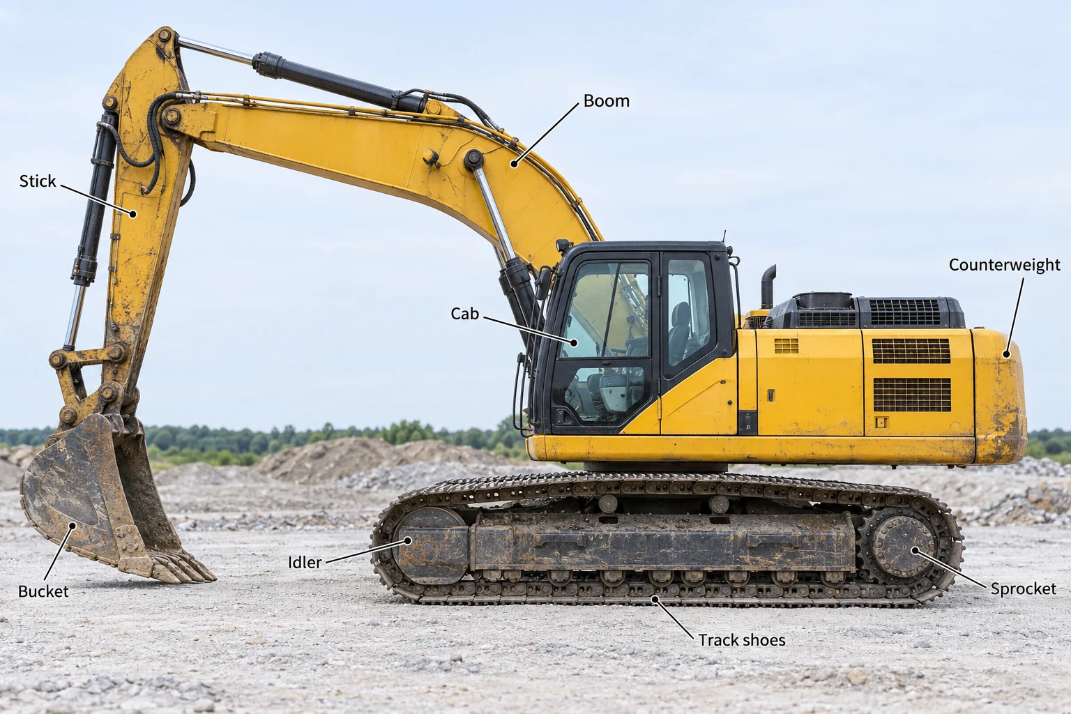
Whole-machine identification view. Visible components are labelled; pumps, valves and the central swivel sit inside the machine and are explained separately below.
The names in this table cover both visible components and the major assemblies behind the body panels. Use the location column to narrow your search before opening a parts book.
| Part or Assembly | Typical Location | Main Function |
|---|---|---|
| Boom | Between upper frame and stick | Positions the front working equipment vertically and carries its load |
| Stick, arm or dipper | Between boom and bucket | Changes reach and draws the bucket toward the machine |
| Bucket | End of stick | Cuts, collects and releases material |
| Bucket linkage | Around stick tip and bucket connection | Converts cylinder travel into bucket rotation |
| Pins and bushings | Articulating joints | Allow controlled pivoting while transmitting loads |
| Boom, stick and bucket cylinders | Along the front equipment | Produce linear force to move the joints |
| Coupler | Between stick/linkage and attachment, if fitted | Provides the attachment connection and locking mechanism |
| Upper frame or revolving frame | Above slew bearing | Supports the cab, power systems and front equipment |
| Cab | On upper frame | Houses the operator, controls and displays |
| Counterweight | Rear of upper structure | Contributes to machine balance |
| Engine | Upper structure under service covers | Drives pumps and auxiliary equipment |
| Main hydraulic pump | Coupled to the power source | Supplies hydraulic flow for work functions |
| Main control valve | Within upper structure | Meters and directs flow to actuators |
| Hydraulic tank | Upper structure | Stores oil and supports fluid conditioning |
| Cooling pack | Upper structure | Transfers heat from coolant, oil and other circuits to air |
| Swing motor and gearbox | Upper structure near slew center | Produce torque to rotate the upper structure |
| Slew bearing or swing bearing | Between upper and lower frames | Supports the rotating structure and its applied loads |
| Center swivel or rotary manifold | Near the rotation axis | Transfers hydraulic fluid between rotating and lower structures |
| Track frame | Along each side of undercarriage | Supports the track-running components |
| Track chain and shoes | Around steel-track undercarriage | Carry ground contact and transmit track movement |
| Rubber track | Around compatible compact-machine undercarriage | Provides a continuous reinforced ground-contact belt |
| Sprocket | At the track drive end | Engages the track and transmits drive torque |
| Idler | At the opposite end of the track loop | Guides the track and moves with the adjustment arrangement |
| Bottom track rollers | Below track frame | Transfer machine load through the lower track run |
| Carrier rollers | Above track frame, where fitted | Support the returning upper track run |
| Track adjuster and recoil assembly | Inside track frame | Establish adjustment and accommodate specified track movement |
| Travel motor and final reduction | At each track drive end | Turn hydraulic power into low-speed track torque |
| Blade | Front of many compact undercarriages | Moves material and provides model-dependent support functions |
The table separates items that suppliers sometimes combine under one name. A complete travel drive can include both a motor and a reduction gearbox. A track group may include chains, shoes and hardware, while a quotation for a chain assembly may exclude shoes. The practical meaning comes from the assembly description and its included components.
Orientation note: the cab can face a different direction from the undercarriage. Describe a track component by its drive end, idler end and the orientation convention in the machine manual. “The wheel behind the cab” becomes ambiguous after the upper structure turns.
Boom, Stick, Bucket and Working-Equipment Parts
Most visible digging movement comes from three connected members: boom, stick and bucket. Their cylinders act through pivots rather than moving the attachment in a straight line. Understanding those connections helps you distinguish a structural member, a hydraulic actuator and a wearing joint when they appear together in a photograph.
Boom and Boom Cylinders
The boom is the main structural member extending from the upper frame. On a conventional machine it rises from the front of the revolving structure and supports the stick at its outer end. Its box-shaped welded construction provides stiffness while leaving space to route pipes, hoses and brackets along the outside.
Boom cylinders connect the frame to the boom at separate pivots. As their length changes, the boom rotates around its base pin. Larger conventional machines commonly have two boom cylinders; smaller machines and specialist arrangements can differ. Cylinder count belongs to the configuration, so it should never be inferred solely from the machine’s general size class.
Digging forces travel backward through the stick into the boom, through its mounting points and into the upper frame. The welded structure, pivot bores and cylinder supports therefore carry related loads through different interfaces. A crack near a bracket, a worn pivot bore and a leaking cylinder require different investigations even when all appear in the same part of the front equipment.
Long-reach, two-piece and specialist booms change the geometry, available working envelope and component arrangement. They can also change cylinder, hose and counterweight requirements. When identifying an unfamiliar machine, photograph the full front configuration before concentrating on a damaged detail. The complete view can reveal an option that the model decal does not describe.
Stick, Arm or Dipper
The stick is the outer structural member between the boom and attachment. “Arm” and “dipper” are common alternative names, although catalog terminology varies. The stick cylinder acts between the boom and stick, changing their angle and moving the attachment inward or outward.
Stick length affects reach and leverage. Extending the digging point farther from the machine changes the moment carried by the structure and the force available at the attachment under a given set of conditions. A longer stick therefore changes more than the location of the bucket teeth; it changes the working combination that must be matched to the machine’s specifications and load chart.
Useful identification details include the stick’s shape, pivot locations, attachment mounts, hose brackets and any casting or assembly marks. The bucket-end joint deserves particular attention because different attachment interfaces can look similar from a distance. Two sticks may accept similar-looking buckets while having different pin diameters, ear spacing or linkage geometry.
The stick carries bending loads as digging force acts away from its pivots. Welded sections, reinforcing plates and the material around the bores form part of that load path. A structural repair therefore needs the applicable manufacturer’s guidance and an assessment of the damaged area; copying a reinforcement from a different stick can change stiffness and redirect stress into another location.
Bucket Shell, Cutting Edge, Teeth and Adapters
The bucket shell carries the material. Its floor, sides, rear profile and attachment ears form the structure, while the cutting edge and ground-engaging tools meet the work first. The result is a combination of load-carrying parts and replaceable wear parts that should be identified separately.
A tooth normally consists of a replaceable tip attached to an adapter using the specified retaining system. The adapter connects the tip to the bucket lip. Side cutters, side protectors, wear strips and other protection may be fitted depending on the bucket design. Some grading or ditch-cleaning buckets use a smooth cutting edge rather than projecting teeth.
These differences change how a bucket enters material and how it wears. A narrow tooth concentrates contact over a smaller area, while a broad smooth edge is useful for finishing. Heavy protection adds mass and changes the bucket assembly’s weight. Choosing the largest or most heavily protected bucket can reduce the payload available for material or make a compact machine less suited to a particular task.
When a tooth is missing, identify both the tip system and the remaining adapter. A replacement tip cannot restore an adapter whose retaining features are worn beyond the applicable limit. Equally, replacing a complete bucket would be excessive if the problem is confined to serviceable wear components. The part breakdown helps establish which level of repair is actually under discussion.
Bucket Linkage, Pins and Bushings
The bucket cylinder usually works through a linkage at the stick tip. The links change the relationship between cylinder stroke and bucket angle. Their geometry influences curling motion and mechanical advantage through the working range; it is more than a collection of brackets connecting the cylinder to the bucket.
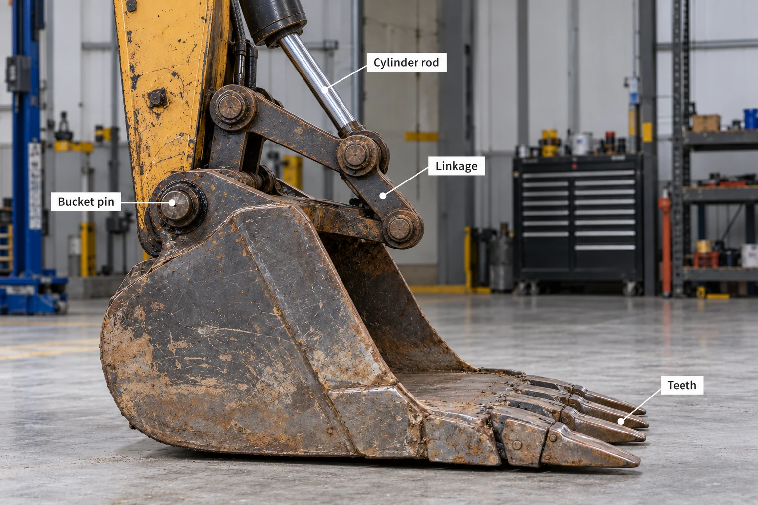
Bucket connection detail. Identify the main bucket pivot separately from the linkage pivots and the cylinder-rod connection.
Pins transmit forces across the joint. Bushings provide replaceable bearing surfaces within the mating components, and seals or dust protection help keep contamination away from the contact area where the design includes them. Retainers prevent the pin from moving out of its intended position; they are separate from the surfaces carrying the main working load.
Looseness can develop at several interfaces. Movement between a pin and bushing has different repair implications from movement between a bushing and a worn structural bore. New pins and bushings address the intended bearing interfaces, while an enlarged or distorted bore can require additional repair. That distinction is useful when a quotation lists only a “pin kit.”
Caterpillar’s linkage pins and bearings information identifies lubrication, contamination and alignment as factors in joint wear. For your machine, use its own service schedule and wear limits rather than transferring a generic greasing interval to every joint and operating condition.
Couplers, Thumbs and Auxiliary Attachments
A quick coupler adds an interface between the excavator and its attachment. Depending on design, it engages attachment pins or a dedicated mounting profile and uses a mechanical or hydraulic locking arrangement. The coupler also adds mass and changes the effective position of the bucket relative to the stick.
A thumb gives the bucket an opposing gripping member. Some thumbs are fixed in selected positions, while others move hydraulically. Their geometry needs to work with the bucket’s path. A cylinder with enough stroke to move the thumb does not, by itself, establish a compatible grasping range or acceptable loads on the mounting structure.
Hydraulic breakers, grapples, augers and tiltrotators introduce further requirements: supply flow, pressure, return arrangements, case-drain provisions where required, control functions and approved machine combinations. Identify the attachment and its interface independently of the excavator. This keeps a machine part, a coupler part and an attachment part from becoming one vague request for an “arm accessory.”
For practical identification, record the attachment make and model, its connection type and the part you need. The excavator’s serial number remains relevant, but the attachment may have its own parts catalog and serial range. Its locking and retention procedures must come from the applicable instructions.
Undercarriage Parts and the Track Drive
The undercarriage carries the upper machine, transfers forces into the ground and provides mobility. Its components work as a group: rollers support and guide, the sprocket drives, and the idler helps establish the track path. Recognizing these distinct jobs prevents a smooth guide wheel from being confused with a drive sprocket.
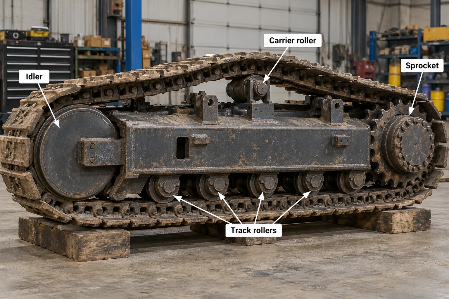
Track-running components shown in a side identification view. Actual roller count, guards, frame construction and adjustment arrangement vary by machine.
Track Frame and Lower Structure
The central lower structure supports the slew bearing and connects the two track frames. Each side frame carries the rollers, idler arrangement and drive components. Together these structures establish alignment and transfer operating loads to the track contact area.
An undercarriage problem can therefore involve more than a worn rotating part. A damaged mounting face, distorted frame or loose attachment can change how a roller sits relative to the track. Replacing the roller without addressing that supporting condition may leave the original cause of uneven contact in place.
Some machines have long-carriage, narrow, wide or variable-width configurations. Shoe width alone does not describe the complete arrangement. Frame length, track gauge, roller layout and option-specific components can differ. A machine advertised with the same model family name may have a different undercarriage group in the catalog.
Steel Track Chains, Shoes and Rubber Pads
In a conventional steel-track assembly, connected links form the articulated chain. Pins and bushings permit articulation and provide the interfaces through which the chain moves around the running gear. Track shoes are attached to the links with the specified hardware. Their ground-facing features provide the contact profile used for traction and support.
The shoes and chain have related but different wear surfaces. A shoe can lose grouser height or suffer damage at its mounting holes while the chain has its own pin, bushing and rail wear. “Worn tracks” is therefore an incomplete description for a repair estimate. It helps to say which surfaces or connections are affected.
Rubber pads may be attached to compatible steel shoes or track arrangements to change ground contact. They are not the same construction as a continuous rubber track. The mounting system, usable clearances and intended surfaces determine whether a pad option is suitable for a particular machine.
Caterpillar’s undercarriage overview groups links, pins, bushings, shoes, rollers, idlers and sprockets as related components. For a parts request, record which of these are included rather than assuming that the word “track” means a complete ready-to-install assembly.
Rubber Tracks
A rubber track is a reinforced continuous belt. Its internal construction carries tension, while drive features engage the sprocket and guide features maintain the intended relationship with the running gear. The tread on the outside provides the ground-contact pattern.
The visible width is only one identifying dimension. Pitch, link or drive-feature count, guide arrangement and internal geometry also affect fit. Similar-looking belts can differ where the sprocket and rollers contact them. Those differences are easy to miss in a side photograph because the critical features are inside the loop.
Rubber tracks are common on compact excavators, but they are not automatically interchangeable with steel-track options. The compatible sprocket, idler and roller arrangement must be established for the actual undercarriage. A track-size code is useful evidence; the machine configuration and approved application information finish the identification.
The outer tread and the inner guide area can tell different stories about damage. Cuts, exposed reinforcement, missing drive features and displaced guides each point to a different affected part of the belt. This article names those areas; repairability and replacement decisions belong to the track manufacturer’s guidance and an inspection of the actual assembly.
Sprockets and Idlers
The sprocket receives torque from the travel reduction and engages the track’s drive features. Its teeth are working contact surfaces. They must match the relevant chain or belt geometry, including the pitch of the engagement.
The idler guides the opposite end of the loop. Its supports allow the intended adjustment movement, and its running surfaces guide the track as it passes around the wheel. Unlike the sprocket, the idler is not the component delivering drive torque to the track.
Wear across this system interacts. A worn chain changes how it contacts a sprocket; a mismatched replacement can put load into the wrong areas. Assessing the condition of connected components helps explain why a supplier may ask about more than the single wheel that looks damaged.
Do not use the boom’s current direction to decide which wheel is the “front.” Identify the sprocket by its drive connection and tooth engagement. The idler-end description then remains clear even when the upper structure has rotated relative to the tracks.
Bottom Rollers and Carrier Rollers
Bottom track rollers sit beneath the frame and transfer load through the lower track run. Their flanges and running surfaces also help guide the track. Carrier rollers, where fitted, support the returning upper run. Their positions expose them to different loading and contact conditions.
The two types can share a broad cylindrical appearance while having different shafts, brackets, flange profiles and mounting arrangements. A diameter measurement alone therefore gives an incomplete identification. A useful photograph includes both the roller and the way it attaches to the frame.
Seals keep lubricant in and contamination out according to the assembly’s design. Leakage or abnormal running behavior calls for inspection, but a general article cannot assign a universal replacement threshold. The relevant wear dimensions and limits are model- and component-specific.
Roller geometry determines where the track makes contact. The running surfaces carry load, while flanges limit lateral movement according to the particular arrangement. A flange rubbing continuously against the wrong surface can be a sign of misalignment or an incorrect component profile. That is why the mounting arrangement and running profile deserve attention alongside outside diameter.
Track Adjuster and Recoil Assembly
The adjustment mechanism establishes the idler position and the specified track sag. On many tracked excavators, a grease-operated cylinder forms part of the arrangement. A recoil spring assembly allows the intended movement when the track system encounters certain loads or material trapped in the running path.
These functions are connected but distinct. The spring is not a substitute for the correct track adjustment, and simply making a loose track tighter does not repair a damaged guide, worn component or failed adjuster. Identify the fault before changing the adjustment.
Safety note: recoil springs and grease-adjustment systems can store substantial energy. Treat covers, retainers and release points as part of a model-specific service procedure. This diagram is an identification aid, not an instruction to dismantle or release a loaded assembly.
Travel Motor and Final Reduction
Each driven track normally has its own hydraulic travel motor and reduction arrangement. The motor converts hydraulic energy into rotation. The gear reduction lowers output speed and increases torque available to the sprocket, within the unit’s design and efficiency limits.
The motor and gearbox may be sold separately or as a combined drive. A complete-looking round unit in a product photo can still omit fittings, sprocket hardware, covers or other installation items. In a catalog, identify the hydraulic motor group and reduction group before comparing assemblies.
Hydraulic oil serving the motor and lubricant inside the reduction gearbox perform different jobs and may occupy separate spaces. That matters when identifying a leak, locating a fill point or interpreting an inspection report. The word “drive oil” is too imprecise unless the relevant circuit or compartment is named.
For a documented example of this separation, Deere’s E-Series excavator brochure lists the travel motor and planetary reduction as distinct system elements. Use that as an example of component roles, not a specification for another model.
Upper Structure, Swing System, Cab and Power Equipment
The upper structure is the complete rotating assembly above the undercarriage. It includes the cab but extends well beyond it: the frame, engine, pumps, tanks, counterweight and front-equipment supports rotate with it. Keeping “cab” and “upper structure” separate makes both diagrams and parts searches more precise.
Upper Frame and Counterweight
The revolving frame provides the structural base for the upper equipment. The boom mounting area, slew-bearing connection, engine supports and body structures all transfer forces through it. Body covers provide access and protection, while the frame carries the primary structural loads.
The counterweight sits at the rear and contributes a balancing moment relative to the front equipment and load. Its effect depends on its mass and distance from the relevant tipping axis, together with the rest of the machine’s geometry and support conditions. It does not make every load at every reach acceptable.
Tail-swing configuration changes the relationship between the upper structure and the track envelope. A compact rear profile helps in restricted spaces, but usable clearances still include the front equipment, attachments and site conditions. “Zero tail swing” should never be read as “nothing on the machine can strike an obstacle.”
Replacement counterweights and structural options require the applicable configuration information. Adding weight to compensate for an unsuitable attachment can create other loads or exceed the intended machine arrangement. The manufacturer’s approved combination and load information establish the relevant limits.
Slew Bearing and Swing Drive
The slew bearing connects the upper and lower structures while allowing relative rotation. It carries axial, radial and overturning loads associated with the rotating machine. A geared ring associated with the bearing arrangement provides the engagement through which the swing drive turns the upper structure.
The swing drive contains the motor and reduction arrangement that produces rotation. Its output pinion engages the ring gear. The bearing supports and guides; the drive supplies torque. These parts cooperate but are not interchangeable names for a single repair item.
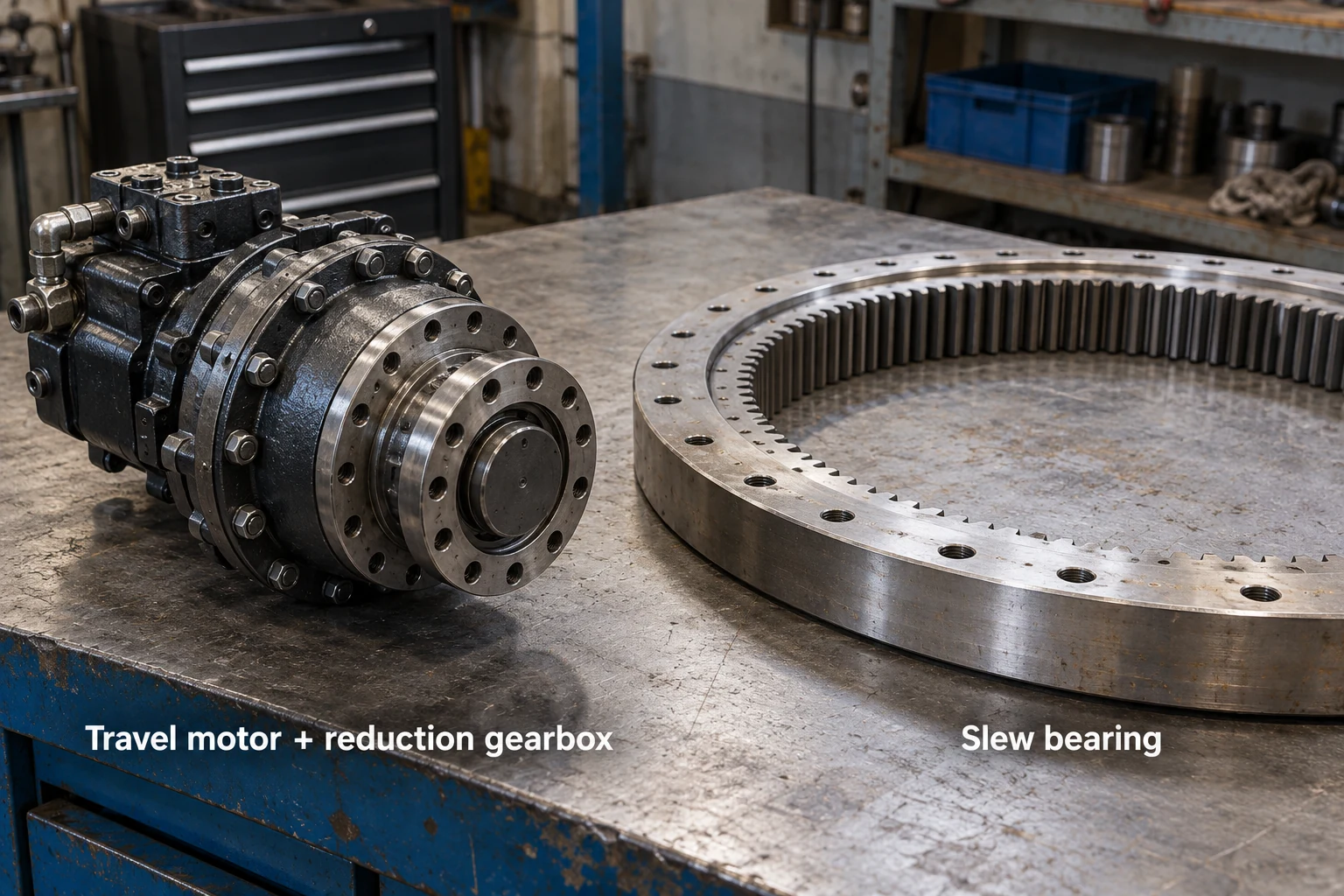
The compact drive assembly converts hydraulic power into rotary torque; the large ring bearing supports a rotating structure. These representative parts are shown separately, not as a matched set.
This distinction helps when describing a complaint. “The machine will not swing” describes a function, while “the slew bearing needs replacement” names a suspected component. The second statement needs evidence that separates bearing condition from motor, gearbox, brake, control and hydraulic problems.
Caterpillar’s swing gear bearing product example illustrates the bearing’s role within the rotating assembly. A particular bearing’s dimensions, bolt pattern and gear geometry belong to its listed application; sharing the name “slew ring” provides no basis for interchanging two rings.
Center Swivel or Rotary Manifold
The upper pumps and valves must supply functions located on the lower structure while the upper structure rotates. A central hydraulic swivel provides fluid passages across that rotating interface. It sits close to the machine’s rotation axis rather than out at the end of a track.
That location explains a relationship that a basic external diagram often misses: the pump is upstairs, the travel motors are downstairs, and a rotating fluid connection links the two. The lines cannot simply wrap around the machine each time the upper structure turns.
The swivel’s hydraulic passages are separate from the slew bearing’s load-carrying function. A rotary electrical connection may also be present where the machine design requires it, but it is a different function and should be identified by the relevant documentation. A nearby component is not necessarily part of the same assembly.
When tracing a line in a catalog, follow its destination and circuit designation. A fluid leak near the slew center can come from a fitting, hose or manifold area; location narrows the search without proving which internal seal or component has failed.
Engine, Intake and Exhaust Equipment
In a conventional diesel hydraulic excavator, the engine drives the hydraulic pumps and supports auxiliary loads. Its air intake, fuel supply, cooling and lubrication systems keep that power source operating under the required conditions. Modern emissions equipment adds further components whose arrangement depends on engine family, market and machine generation.
Air-cleaner housings, filter elements, intake hoses and charge-air plumbing are separate parts. A turbocharged engine can also have a charge-air cooler between the compressor and engine intake. The radiator, charge-air cooler and hydraulic oil cooler may share a cooling pack while serving different fluids or air circuits.
The engine can have its own model and serial number in addition to the excavator’s product identification number. That distinction becomes valuable when the same machine family was offered with different engines or when a replacement engine has been installed. The machine record and the component record should tell a consistent story.
Engine speed and hydraulic demand interact during work. The engine governor and pump-control arrangement coordinate available power with the requested functions. A machine that idles smoothly but struggles during combined movements therefore needs its operating conditions described accurately: which functions were used, whether the engine speed changed and whether the behavior appears only after warming up.
Cooling Pack, Fan and Filters
The cooling pack transfers heat from the machine’s working fluids and air circuits to the surrounding air. The engine radiator handles coolant, while an oil cooler serves the specified oil circuit. Fan, shrouds, screens and ducting influence how air passes through the heat exchangers.
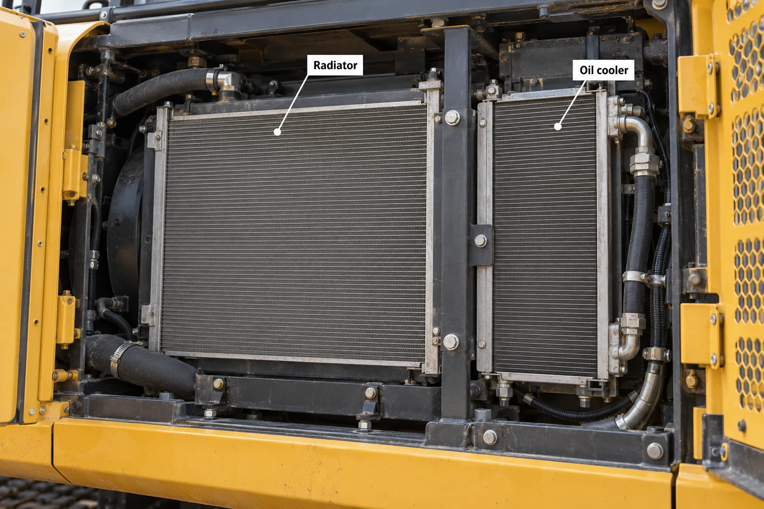
Cooling-pack identification example. Hose routing and the actual service diagram distinguish the circuits; panel position alone is not a universal identification rule.
A restriction in front of one exchanger can affect airflow through another when they are arranged in a stack. Bent fins, debris, loose seals around the pack or fan-control problems can therefore influence cooling without a failed radiator core. The physical arrangement is worth understanding before reducing every overheating complaint to a single replacement part.
Filters also belong to specific circuits. Engine oil, fuel, hydraulic return, pilot and other filters can look similar while having different media, flow characteristics, bypass arrangements and mounting requirements. Match the actual application and part identity rather than choosing by thread fit or canister size.
Some screens and breathers are less obvious in a whole-machine photo but still matter to system function. A hydraulic tank breather, for example, is part of the tank’s air-management arrangement. Identifying it as a breather keeps it from being confused with a filler plug or an ordinary cap.
Cab, Controls and Electrical Components
The cab contains the operator’s seat, joysticks, pedals, switches and display. The control devices communicate the requested movement; hydraulic pilot circuits, electrical signals or a combination implement that request depending on the machine design. The joystick itself is not a direct mechanical link to every cylinder.
Electrical components include the battery, starter, alternator, fuses, relays, wiring harnesses, controllers and sensors. A sensor may report temperature, pressure, position or another condition. A controller uses inputs and its programmed logic to regulate functions, display warnings or command an actuator.
Connectors deserve attention when identifying a component. Housing shape, pin count, keying and location help establish what the part connects to, but electrical function still comes from the diagram and application information. Similar plugs can carry different signals, and replacement controllers may require software or configuration work.
Cab glazing, access steps, mirrors, cameras, latches and interior components are additional service items. Protective structures and rated glazing have functions beyond appearance. Their replacement specifications should preserve the intended protection and installation arrangement rather than merely match an external shape.
How the Hydraulic System Makes the Parts Work Together
Hydraulics connects the excavator’s visible movement to components largely hidden inside the upper structure. The useful distinction is between producing flow, directing it and converting it into motion. Once those three jobs are clear, pump, valve, cylinder and motor stop sounding like interchangeable explanations for the same movement.
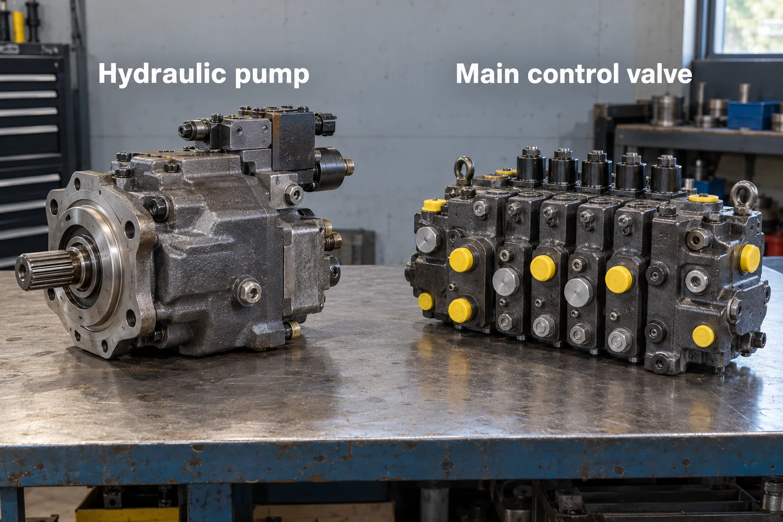
Pump and valve identification. The pump receives mechanical input; the control valve distributes and meters hydraulic flow. This is a component comparison, not a piping diagram.
From Engine Power to Controlled Movement
The pump converts mechanical input into hydraulic flow. System pressure develops in response to the resistance and load acting on that flow, within the control and protection arrangements. The main control valve directs and meters flow toward the selected cylinder or motor, while return paths allow fluid to leave the other side of the working component.
Cylinders create linear force and movement. Motors create rotary torque and movement. The cylinders then act through the boom, stick or bucket geometry, while motors serve functions such as swing and travel. A hydraulic motor can therefore perform a very different physical job from a cylinder despite using the same general power medium.
Machine designs vary in pump arrangements, valve architecture and control strategy. Volvo Construction Equipment & Services’ hydraulics explanation describes electric-over-hydraulic control as part of newer Volvo systems. That example shows why an older pilot-controlled machine and a newer electronic-control machine should not be assumed to have identical control components.
The tank, filters and cooler support the working circuit. Oil must arrive at the intended condition and return through the appropriate path. Hoses and pipes provide the connections, while valves and other devices manage routing, pressure and specialized functions. A complete circuit diagram also shows features that a simplified engine-to-cylinder explanation leaves out.
Pressure, Flow and Force: A Worked Example
Pressure and flow explain different aspects of movement. With the relevant assumptions, cylinder force follows pressure multiplied by effective piston area, while piston speed follows flow divided by that area. Parker’s mobile-cylinder reference explains these basic relationships.
For a teaching example, assume a cylinder has an 80 mm bore, receives 200 bar at its full piston face and has negligible opposing pressure and friction. These are chosen example values, not a specification or adjustment recommendation for an excavator.
- Piston area = π × 0.08² ÷ 4 = approximately 0.00503 m².
- Pressure = 200 bar = 20,000,000 Pa.
- Ideal extension force = pressure × area = approximately 100,500 N, or 100.5 kN.
- At 60 L/min, incoming flow is 0.001 m³/s; ideal piston speed = flow ÷ area = approximately 0.199 m/s.
Those results describe the cylinder under the stated assumptions. Bucket force also depends on the linkage position and leverage, and usable lifting capacity depends on the machine’s rated configuration and stability. Friction, pressure on the other side of the piston, flow losses and control behavior change the real result.
The comparison gives you a useful way to interpret specifications: additional flow can increase actuator speed under suitable conditions, while pressure and area influence available force. Neither figure by itself defines an excavator’s overall digging performance.
Follow One Bucket-Curl Movement
Consider a bucket-curl command while the machine is stationary. The operator requests movement through the control system. The relevant valve function meters flow to the bucket cylinder, and the opposite cylinder chamber has an appropriate return path. The piston and rod change position, the linkage turns, and the bucket rotates around its main pivot.
Resistance at the teeth travels through the bucket structure and joints into the stick and boom. At the same time, hydraulic loading changes within the circuit. This creates two connected paths: an energy path through engine, pump, valve and cylinder, and a structural load path through the working equipment and machine frame.
That distinction explains why the same complaint can arise in different systems. Excessive joint movement affects bucket control mechanically. Restricted or insufficient hydraulic delivery affects motion differently. An operator’s report should describe what happens, under which movement and conditions, rather than jumping directly to a named replacement assembly.
Follow Travel and Swing Separately
For travel, the selected hydraulic function sends flow through the relevant circuit and rotating connection to a travel motor. The motor drives its reduction gearbox, the sprocket engages the track, and the track’s contact with the ground moves the machine. Steering depends on the relative action of the two track drives and their interaction with the ground.
For swing, the hydraulic motor and reduction turn the swing pinion against the ring gear while the slew bearing supports the rotating structure. The tracks can remain stationary throughout this movement. A swing complaint and a travel complaint therefore lead to different component groups even though both use hydraulic motors.
Combined movements add another layer: multiple actuators compete for or share available power and flow according to the machine’s design. Slower action during simultaneous commands can have a different explanation from a single function that is slow when operated alone. The service procedure establishes how to compare those conditions safely and meaningfully.
Mini Excavators and Other Configurations That Change the Diagram
The same basic component families appear across many excavators, but layout and interfaces change with the machine’s job. Treat the conventional crawler view as a starting point. The additional features below explain why a compact-machine photo or wheeled-machine catalog may not match it exactly.
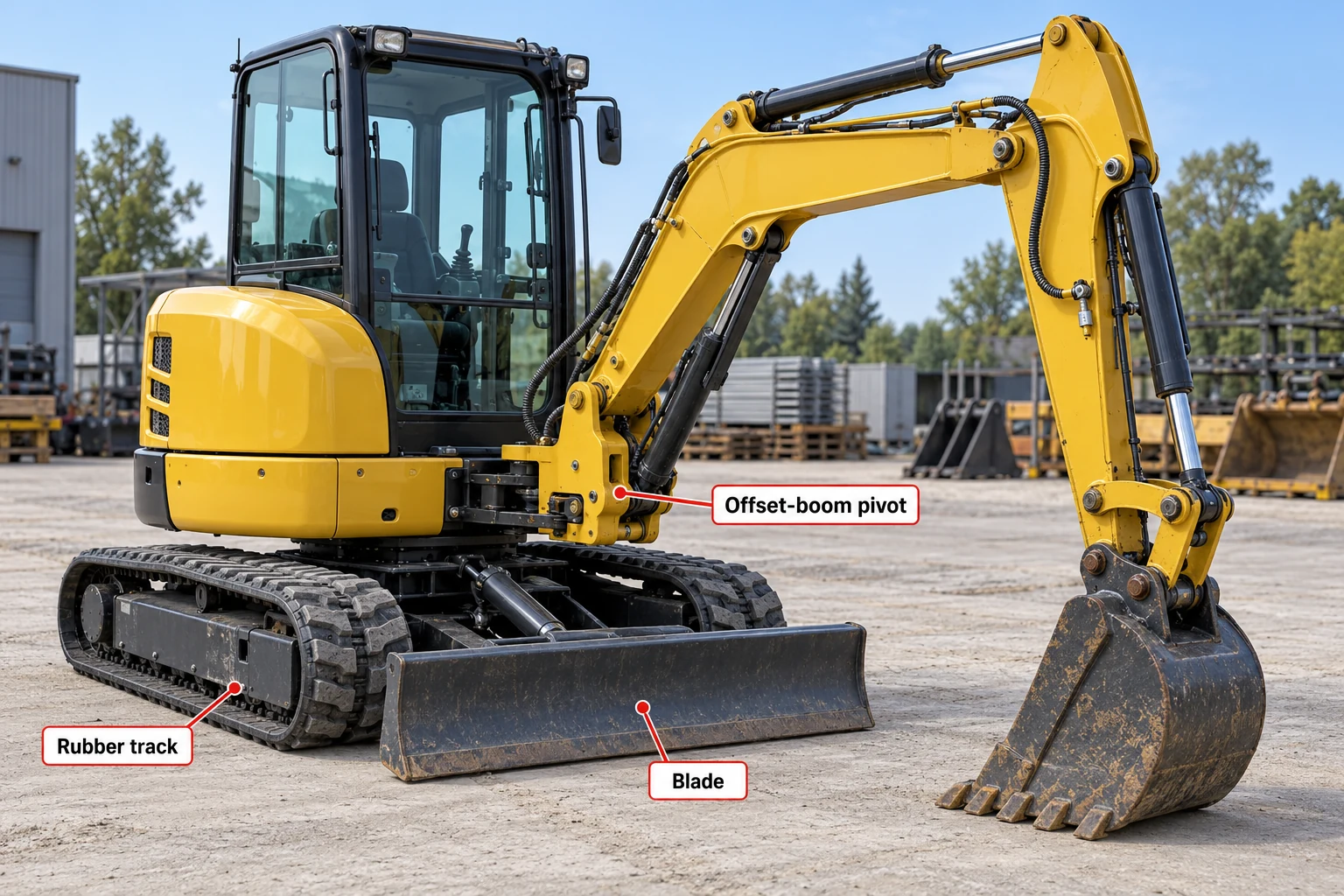
Compact-machine example showing three features worth identifying separately: the rubber-track undercarriage, blade and offset-boom connection.
Mini Excavator Features
Many compact excavators have a boom-offset mechanism that pivots the front equipment relative to the upper structure. This movement is separate from swinging the entire upper structure on the slew bearing. Its own pivot, cylinder and mounting components can appear in a different catalog group from the main boom-lift components.
A blade attaches to the lower structure and has its own linkage and cylinder arrangement. Depending on the model, options can add angling or other functions. Its operating position and permitted use come from the machine instructions and relevant load information.
Some small machines also use a retractable undercarriage. Bobcat’s compact-excavator features guide describes the narrower transport arrangement and extended working arrangement on equipped models. This feature introduces frame and adjustment components absent from a fixed-width machine. It should be recorded as part of the configuration when identifying undercarriage parts.
Wheeled, Long-Reach and Specialist Machines
A wheeled excavator replaces the crawler running gear with a wheel-based chassis, axles and associated drive and steering equipment. Stabilizers or a blade may be present. The upper hydraulic working equipment can remain familiar while the mobility system requires a substantially different parts diagram.
Long-reach and material-handling configurations change the front structure and its operating envelope. A demolition machine may add specialized protection or a different front arrangement. These changes can affect hoses, cylinders, counterweights, protective equipment and mounting groups.
Electric excavators also change the power-source section. An electric motor and its energy supply can replace the diesel engine arrangement while hydraulic working functions remain. A guide organized around component roles accommodates this difference more accurately than assuming every excavator has the same fuel, exhaust and engine components.
Practical tip: take one wide photograph of the complete machine and one of its identification plate before taking close-ups. The wide photograph records options and configuration; the plate identifies the machine; close-ups identify the component. Together they answer different questions.
From a Component Name to the Correct Parts Diagram
The next step after naming a component is selecting the right document. A whole-machine image, an exploded parts view and a hydraulic schematic contain different information. Choosing the appropriate one prevents a clear-looking illustration from being used for a job it cannot support.
| Document | Question It Answers | Information to Look For |
|---|---|---|
| Whole-machine identification diagram | What is the visible part called? | Location, broad function and neighboring assemblies |
| Exploded parts illustration | What individual items make up this assembly? | Callout references linked to a parts list |
| Parts list or catalog table | Which replacement identity applies? | Part number, quantity, remarks and applicability |
| Hydraulic schematic | How are fluid paths and devices connected? | Symbols, ports, connections and circuit functions |
| Electrical diagram | How are electrical components connected? | Wire identities, connectors, circuits and devices |
| Service procedure | How is the work performed and checked? | Preparation, tools, sequence, settings and acceptance limits |
Use the whole-machine diagram to find your starting assembly, then move to the corresponding catalog or technical document. An exploded view’s visual spacing helps show separate items; it should not be treated as a universal disassembly order.
Reading the Callout and Parts-List Relationship
A number beside an illustrated item usually refers to a row in the accompanying list. The ordering identity is the part number in that row, subject to its notes and application. One callout can have more than one possible row when configurations or serial ranges differ.
Deere’s official Parts Lookup FAQ describes searching by model or product identification number and navigating illustrations and part lists. It is a useful example of a manufacturer-organized route from machine identity to an assembly, rather than a visual match across unrelated product listings.
Imagine a catalog illustration with a bucket pivot marked “Item 7.” That item number alone says nothing about the correct pin diameter or part number. The corresponding table may identify a pin, while neighboring rows identify seals, bushings and retainers. The ordering decision comes from the applicable rows and notes, not from the size of the drawn circle.
An old casting mark can also differ from a current orderable assembly number. Record it because it may help identification, but keep it separate from a confirmed replacement number. Supersessions, revised assemblies and kit contents belong to the catalog or supplier’s documented explanation.
A Short Identification Record That Keeps the Details Together
For an unfamiliar component, collect the information in this order. The sequence moves from the machine to the assembly and then to the individual item, reducing the chance of matching a detail from the wrong configuration.
- Machine: manufacturer, complete model designation and product identification or serial number.
- Configuration: relevant front equipment, undercarriage, engine or attachment option.
- Component: its name, position and any separate manufacturer plate or assembly number.
- Catalog reference: catalog identity, assembly title, illustration and item callout.
- Applicable entry: part number, description, quantity and relevant remarks.
- Supporting images: an overall view, mounting view and readable identifier close-up.
Measurements become useful when the catalog or supplier needs to distinguish plausible alternatives. Include units and show the measurement endpoints. A loose number such as “80” can refer to a bore, pin, width, nominal size or model code; a dimensioned photograph makes the intended feature clear.
You can download a component identification record to keep these details in one place. It is a blank worksheet for your machine, not a replacement-parts database.
FAQs on Excavator Parts
These questions address naming and configuration issues that often remain after the main components have been identified.
Is the Arm the Same as the Boom?
The stick or arm is usually the outer member connecting the boom to the bucket. The boom is the larger inner member connected to the upper frame. Everyday speech sometimes uses “arm” for the whole front assembly, so include the joint locations or a photograph when the distinction matters. In a parts catalog, use the manufacturer’s actual assembly name.
Which Parts Rotate When an Excavator Swings?
The upper frame, cab, counterweight, engine and front working equipment rotate together relative to the lower structure. The slew bearing supports this relative movement, and the swing drive produces it. On many mini excavators, offset-boom movement provides an additional separate pivot without requiring the whole upper structure to turn.
Does a Final Drive Always Include the Travel Motor?
The term is used for both a combined travel assembly and, in some listings, the reduction gearbox alone. Read the component list and assembly drawing. Establish whether the motor, brake components, fittings and related installation parts are included. The product name should be treated as the beginning of that comparison rather than the complete supply description.
Can Two Excavators Use the Same Replacement Part?
They can, but shared appearance or brand is insufficient to establish that relationship. A documented common part number, applicable supersession or verified cross-reference is the useful evidence. Machine generation, serial range, option groups and separately identified components can change the answer even within a model family.
Which Diagram Should I Use for a Hydraulic Problem?
A whole-machine picture helps locate the pump, valve and actuator. A hydraulic schematic shows how their circuits connect, and the service procedure supplies the test conditions and limits. Use those documents together for the actual machine. A component’s position in a generic diagram cannot determine its port function or establish a safe pressure-test procedure.
Conclusion
Begin with the part’s location, then identify its role: carrying load, guiding movement, supplying hydraulic power or controlling a function. Follow its connections to understand which assembly contains it. For a replacement, carry that identification into the applicable catalog and record the complete part entry, including configuration and supply scope. That progression turns a familiar-looking component into a clear, usable parts request.
Illustrations: original AI-generated educational visuals of representative equipment and components. Model-specific layouts, dimensions and application details come from the relevant manufacturer’s documents. Technical sources reviewed October 29, 2026.
Continue with our rubber track measurement guide when you need width, pitch and link count. For the two roller positions shown in the undercarriage, see track rollers versus carrier rollers.